Tutor: Click a real component to highlight where it should be placed or connected.
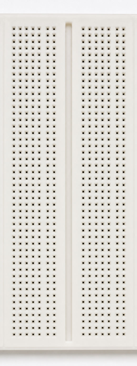
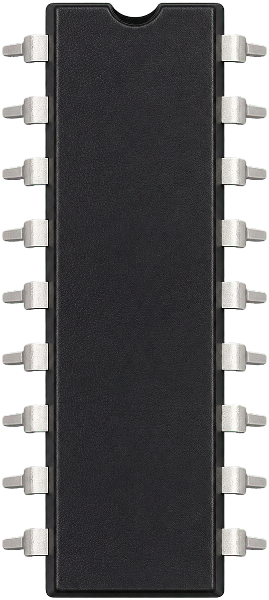 74HC75
Latch1-DCLK+5 VLatch2-D
Latch1-QCLK'0 VLatch2-Q
74HC75
Latch1-DCLK+5 VLatch2-D
Latch1-QCLK'0 VLatch2-Q
Test the D Flip-Flop
Choose D, apply a clock pulse, or activate Q′ feedback and the repeating clock.
D
CLK
Q
Predict before testing
Choose the value you predict Q will have after the next active clock pulse.
Make a prediction to enable the next clock pulse.
Guided test: 0 of 2 input cases completed
Loop behavior: When Loop is on, Q′ is connected to D. Each active clock pulse therefore toggles Q.